Have you ever been challenged to take multiple measurements in a short period of time?
In this article we will discuss the key features of the digitizerNETBOX, an LXI digitizer instrument, and demonstrate how it can make real world measurements on an air compressor. We'll show how to install and connect the instrument and then set up the measurement with the included software - all within a few minutes.
 The Spectrum digtizerNETBOX is a series of table-top instruments with a rack mount option which offers from two to forty-eight channels, available with 14 or 16 bit resolution digitizers and with maximum sample rates from 200kS/s to 500 MS/s. Each is a self-contained package with a GBit Ethernet based LXI compatible interface. There are 59 different model configurations to match a wide number of measurement needs. Each of these instruments can be operational within minutes of unpacking. Power it up, connect your internet cable, load the included software, and go!
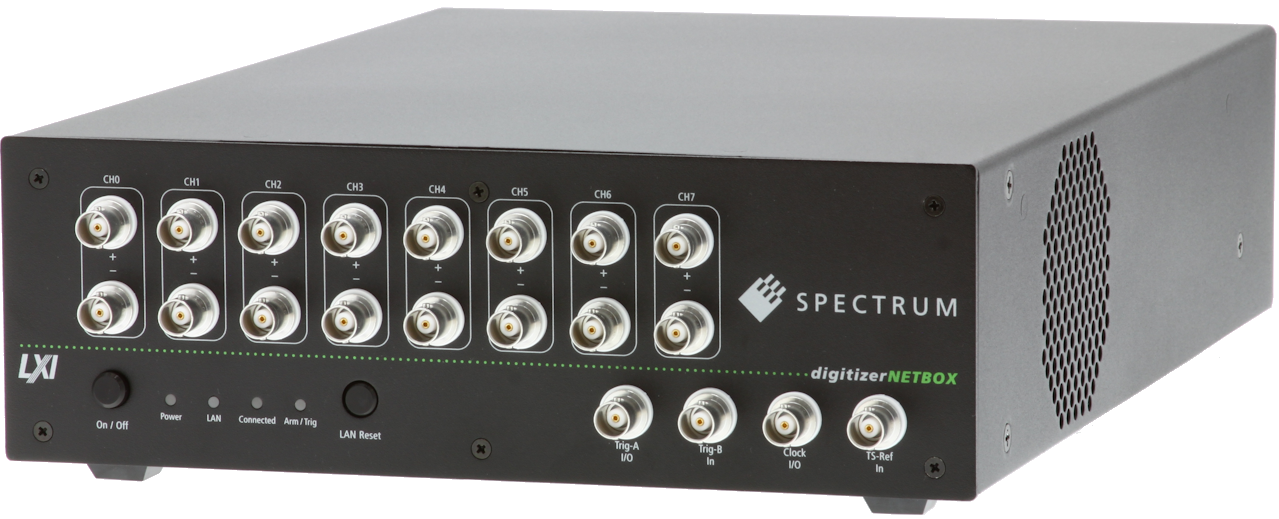
Figure 1 shows a typical digitizerNETBOX.
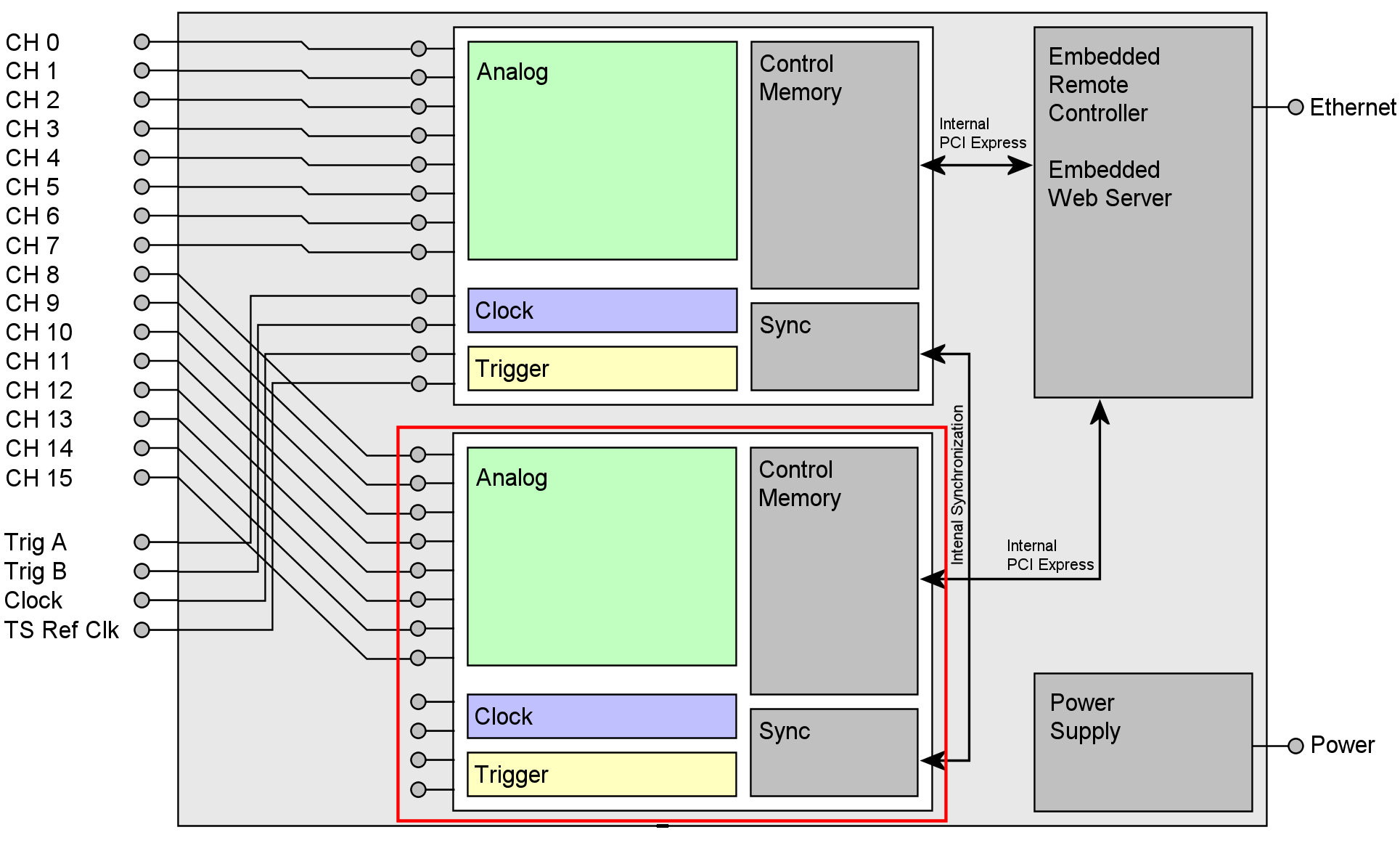
DigitizerNETBOX Block Diagram
The heart of the digitizerNETBOX is the proven Spectrum digitizer hardware offering low noise analog front-ends, multiple acquisition modes, flexible triggering, and large acquisition memories. Figure 2 shows the block diagram of a 16 channel digitizerNETBOX which uses two 8 channel digitizers. Each channel has its own analog front-end and ADC, fully synchronized with a common sampling clock. A versatile triggering engine offers a number of triggering modes based on channel inputs or external trigger sources. Digitizer outputs are linked to an embedded remote controller/webserver via a high speed PCI Express bus. The whole unit is powered by a high quality power source. Either an AC or, for portable applications, an optional DC power supply is available.
 Models are available in eight families with sampling rates of 500, 250, 130, 60/30, 10, 3, 1 and 0.2 MS/s. The number of channels available varies from 2 to 48 dependent on the family selected. Resolution is 16 bits for digitizers with maximum sampling rates of 250 MS/s. The 500 MS/s digitizers are 14 bit devices. Each internal digitizer includes at least 512 MSamples of acquisition memory.
Data transfer and control is via an LXI (LAN eXtensions for Instrumentation) interface based on 1000BaseT Ethernet, supporting direct, local area network (LAN) and wide area network (WAN) computer interface. LXI offers reliable Ethernet communication, instrument interoperability, standard drivers, and an enhanced web interface. The digitizerNETBOX is a full LXI instrument, following LXI Core specification 2011, which is able to show the status of the box along with the current acquisition data.
The digitizerNETBOX is supported by drivers and examples for common computer programming languages as well as IVI, LabVIEW, and MATLAB. A professional version of Spectrum's SBench 6, -a powerful and intuitive interactive measurement software package, is included with the instrument. This program offers hardware setup, data display, and time, frequency and statistical domain analysis functions on Windows or LINUX operating systems.
DigitizerNETBOX applications
The digitizerNETBOX can be used for many measurement applications. Units configured with the DC power supply and directly coupled with a laptop computer are ideal for mobile or service measurements powered from a vehicles battery. These applications would include in-vehicle measurements.
Using the power of the LXI instrument interface the digitizerNETBOX can also be located in a lab where multiple users can individually access it via LAN. The digitizerNETBOX gets its IP address from a standard DHCP server and can be reached over an Ethernet connection like any other TCP/IP device. Examples include control room situations and factory floor monitoring operations. It is also useful in people unfriendly environments including those with excess noise, chemicals, explosives, radiation or high-voltage.
Connecting the digitizerNETBOX to a wide area network (WAN) allows global access from offsite analysis locations. This type of operation includes collaborative analysis involving multiple sites and is ideal for large projects.
DigitizerNETBOX features
Front-Ends
Analog inputs to the digitizerNETBOX each have their own signal conditioning and analog to digital converter (ADC). Depending on the model there can be up to 48 individual channels each with remotely programmable coupling, termination, and input voltage range. Select between 50Ω or 1 MΩ input termination, AC or DC coupling and the input voltage range can be between ±50 mV to ±10 V full scale (model dependent).
Clock
The sample clock for the digitizerNETBOX may be either internal or from an external source. The internal clock uses a phased lock loop (PLL) that allows the clock to be set with great precision. The external clock input can be directly applied as the sampling clock or routed as a reference clock to the PLL.
Acquisition Modes
Digitizers offer two operating modes. The standard mode uses the internal acquisition memory as a ring buffer just like an oscilloscope. Data is written in the ring memory of the digitizer until a trigger event occurs. After the trigger, post-trigger values are recorded. This results in both pre and post-trigger values being included in the recorded data.
The second method is to use the memory in a FIFO (first in-first out) mode. This is a streaming mode which is designed for continuous data transfer between the digitizer and an external host computer. The control of the data stream is handled automatically, by the driver. The complete installed acquisition memory is used as a buffer, providing reliable data streaming at rates up to the limit of the Ethernet connection.
The standard and FIFO modes each offer three multiple recording methods which provide more efficient use of the acquisition memory in low duty cycle measurement applications. Low duty cycle applications include those which have short duration events of interest followed by long quiescent intervals. The acquisition methods optimized for the capture of this type of signal are Multiple Recording (segment) mode, Gated mode, and ABA (dual time base) acquisition. All of these modes segment the memory and make multiple acquisitions within it. The dual time base ABA mode reduces the sampling rate between triggers saving memory space but providing a view of what is happening in the dead-time between triggers.
Let's take a look at how these unique acquisition modes work. The Multiple Recording (segmented) mode allows the recording of multiple trigger events with an extremely short re-arm time. The acquisition memory is divided into several segments of equal size. One segment is filled for each trigger event. The acquisition stops between segments. The number of acquired segments is only limited by the memory used and is unlimited when using FIFO mode. Significant data associated with multiple triggers is stored in the acquisition memory in the contiguous segments. Data associated with the dead-time between events is not recorded. Each trigger event is time stamped so the precise location of each trigger is known.
Gated acquisition uses the state of a gating (enabling) signal, which can be either another channel or an external trigger input, to start and stop the sampling process. Data is only written to memory while the gate is active. In Gated mode the timestamps mark the opening and closing of the gate not including the pre and post gate acquisition interval. The number of acquired gate segments is limited by the acquisition memory and is only limited by the host memory when using FIFO mode.
ABA mode is a dual time base acquisition combining a fast acquisition on trigger events (B time base) with a slow sampling rate (A time base) between triggers. The ABA mode works like a slow data logger combined with a fast digitizer. The exact position of the trigger events is marked with timestamps as in the Multiple Recording mode.
Triggering
Triggers synchronize data acquisition with external events. Effective use of a digitizer requires great flexibility in device triggering. Trigger sources include the acquisition channels and multiple external trigger inputs. For maximum trigger flexibility these inputs along with a rearm capability can be combined logically to produce advanced trigger states. The principal trigger sources contain dual trigger level comparators and support multiple trigger modes. These include single and dual slope edge triggers, re-arm (hysteresis) triggers, window triggers, and for the multiple source trigger there are related trigger gate generators. Logical AND or OR functions can be applied with multiple trigger sources to provide further flexibility in the trigger function.
All trigger events can be time stamped with a resolution of 1 sample. A timestamp reference signal from a GPS receiver or an IRIG-B receiver can also be fed into the unit.
Example Application
 The best feature of the digitizerNETBOX is the ease with which it can be setup and used. The following application for a Spectrum Model DN2.496-04 (4 channel, 16 bit, 60 MS/s) digitizerNETBOX involved measurements on a small air compressor. The digitizerNETBOX was unpacked and connected to a local area network. Device drivers, the Spectrum Control Center, and the SBench 6 software are installed in the unit, so there is no need to download or use a DVD.
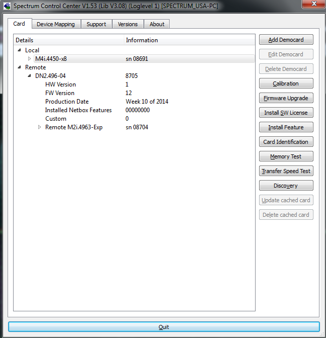
The Spectrum Control center (Figure 3) has a discovery function that helps identify any digitizerNETBOX connected to your computer LAN. Simply press the Discovery button in the Spectrum Control Center and the unit will show up on your computer.
Within fifteen minutes of unpacking the unit it was ready to make measurements.
The air compressor was somewhat noisy so it was setup in a separate room along with the digitizerNETBOX. It was connected via a LAN and the measurement was remotely controlled using Spectrum's SBench 6 interactive measurement software package.
The air compressor was fitted with a pressure transducer, an accelerometer, and an instrumentation microphone which were connected via appropriate power sources to the digitizerNETBOX. Transducer sensitivities were 100mV/psi for the pressure transducer, 10 mV/G for the accelerometer, and 42mV/Pa for the microphone. These sensitivities were used to program SBench 6 so that readings of pressure and sound pressure would be in Pascal and acceleration would read in G's.
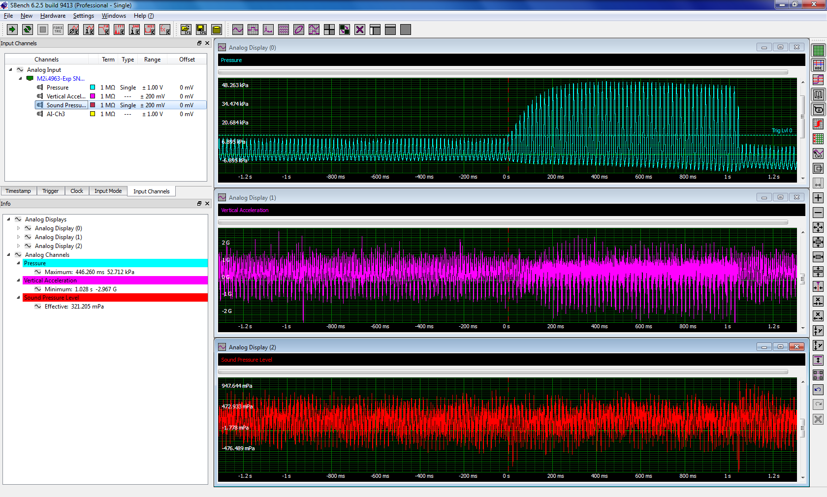
 Figure 4 shows the result of a measurement of all three parameters when the discharge port of the compressor was closed in order to measure the maximum pressure available. The digitizerNETBOX was triggered on the increase of pressure which appears in the channel titled Pressure in the top grid of the display. Immediately below that, the acceleration channel reads the vertical acceleration. The waveform at the very bottom, shows the variation in sound pressure level.
The measurement trigger occurred when the pressure exceeded 13.7 kPa. The output port was closed for one second and the peak pressure recorded was 52.7 kPa as measured using SBench 6's measurement calculation capability. During the time that the discharge port is closed the vibration level increases with a maximum downward acceleration of 3 G's. This is again read using SBench 6's minimum parameter on the vertical acceleration channel.
The sound pressure level remains relatively unchanged until the discharge port is closed and again when it is opened. It is picking up sound of the valve which closes the port. The effective (rms) sound level is recorded as 321 mPa which explains the uncomfortable noise level when the compressor is running outside of its enclosure.
Conclusion
The digitizerNETBOX is a handy instrument to have around. It's set up quickly and provides excellent measurements for as many channels of data as you need. Compared with card based digitizers it's much simpler to set-up, can be shared by multiple users or easily taken around to different locations. There is no need to open a PC chassis for installation or to worry about the PC's chassis size, power supply or cooling. The digitizerNETBOX runs with any PC or even a Laptop or notebook computer.