THIS PRODUCT IS END-OF-LIFE. Show more about end-life-products policy.
Recommended product:
Product:
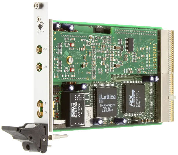
MX.4030
14 bit transient recorder
Description:
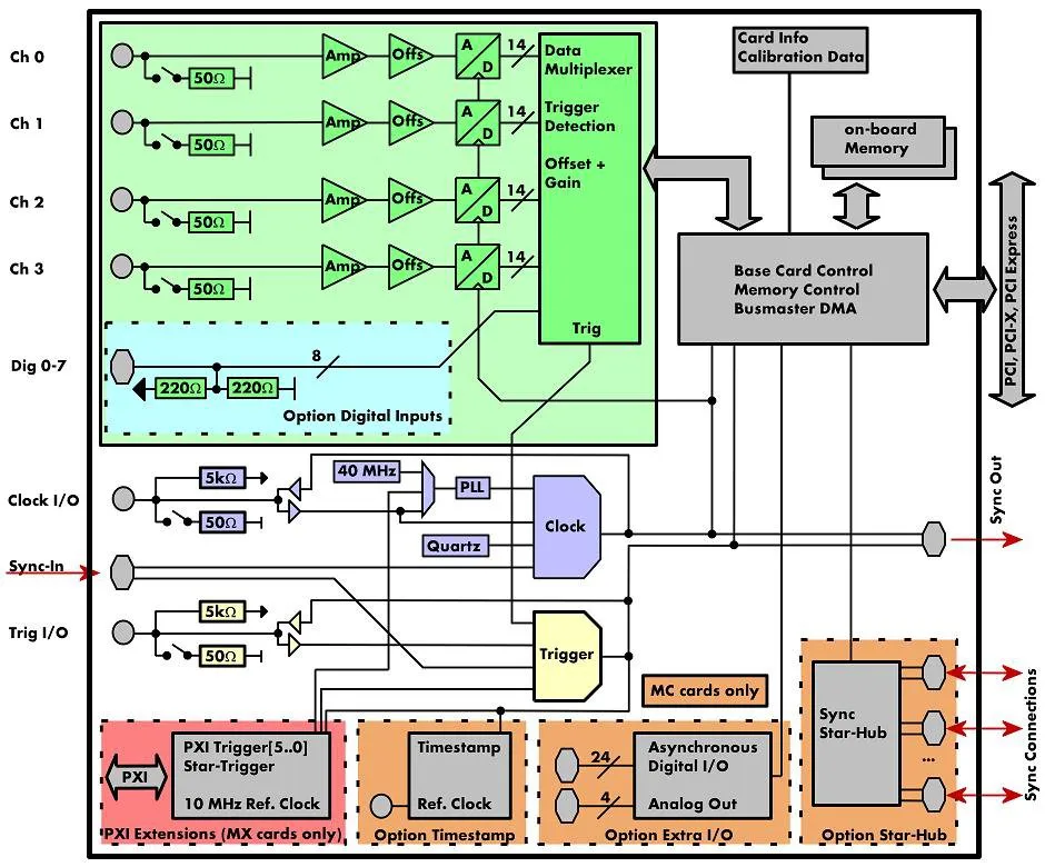
The MX.40xx is best suitable for applications that need high sampling rates as well as a maximum signal dynamic. These boards offer a resolution 4 times higher than 12 bit boards. On the MX.40xx every channel has its own amplifier and A/D converter. Each input channel can be adapted to a wide variety of signal sources. This is done by software selecting a matching input range, an input impedance and an individual input offset. The user will find easily a matching solution from the six offered models. These versions are working with sampling rates of 20 MS/s or 50 MS/s and have one or two channels and can also be updated to a multi-channel system using the internal synchronization bus. Data is written in the internal 8 MSamples up to 64 MSample large memory. This memory can also be used as a FIFO buffer. In FIFO mode data can be transferred on-line directly into the PC RAM or to hard disk.
Facts & Features:
- Up to 50 MS/s on 1 channel
- Simultaneously sampling on all channels
- 6 input ranges: +/- 200 mV up to +/- 10 V
- Up to 64 MSample on-board memory
- 32 MSample standard memory installed
- Window and pulsewidth trigger
- Input offset up to +/-200%
- Synchronization possible
- CompactPCI/PXI 3U compatible
- Supporting PXI star trigger
- Supporting PXI trigger bus
- Supporting PXI reference clock
Application examples:
- Explosion Tests
- Ignition Voltage Tests
- IQ Base Signal Acquisition (replay with MX.60xx series)
- NMR (Nuclear Magnetic Resonance)

FIFO mode
The FIFO mode is designed for continuous data transfer between measurement board and PC memory (with up to 100 MByte/s) or hard disk. The control of the data stream is done automatically by the driver on interrupt request. The complete installed on-board memory is used for buffer data, making the continuous streaming extremely reliable.PXI Star Trigger Card (Optional)
The MX.9010 is a special PXI star trigger card designed for the Spectrum PXI products. It allows to route clock and trigger synchronously to all PXI slots that are connected to the star trigger slot. The PXI reference clock is overwritten and external trigger events are synchronized to the sampling clock.

Channel Trigger
The data acquisition boards offer a wide variety of trigger modes. Besides the standard signal checking for level and edge as known from oscilloscopes it's also possible to define a window trigger. Trigger conditions can be combined with logical conjunctions like OR to adopt to different application scenarios.

External Trigger
All boards can be triggered using an external TTL signal. It's possible to use positive or negative edge also in combination with a programmable pulse width. An internally recognized trigger event can - when activated by software - be routed to the trigger connector to start external instruments.


PXI Trigger
The Spectrum cards support star trigger as well as the PXI trigger bus. using a simple software commend one or more trigger lines can be used as trigger source. This feature allows the easy setup of OR connected triggers from different cards.
Timestamp
The timestamp option writes the time positions of the trigger events in an extra memory. The timestamps are relative to the start of recording, a defined zero time, externally synchronized to a radio clock, or a GPS receiver. With this option acquisitions of systems on different locations can be set in a precise time relation.
External Clock
Using a dedicated connector a sampling clock can be fed in from an external system. It's also possible to output the internally used sampling clock to synchronize external equipment to this clock.

PXI Reference Clock
The card is able to use the 10 MHz reference clock that is supplied by the PXI system. Enabled by software the PXI reference clock is feeded in the on-board PLL. This feature allows the cards to run with a fixed phase relation.
Reference Clock
The option to use a precise external reference clock (normally 10 MHz) is necessary to synchronize the board for high-quality measurements with external equipment (like a signal source). It's also possible to enhance the quality of the sampling clock in this way. The driver automatically generates the requested sampling clock from the fed in reference clock.
Digital Inputs (Optional)
This option acquires additional synchronous digital channels phase-stable with the analog data. When the option is installed and activated additional digital inputs are stored in the unused bits of each ADC word (2 digital inputs on 14 bit A/D and 4 digital inputs on 12 bit A/D)

Programmable Input Amplifiers
The analog inputs can be adapted to real world signals using a wide variety of settings that are individual for each channel. By using software commands the input termination can be changed between 50 Ohm and 1 MOhm and one can select an input range matching the real world signal.
Programmable Input Offset
Most of the Spectrum A/D cards offer a user programmable signal offset opening the Spectrum boards to a wide variety of setups. The signal offset at least covers a range of +/-100 % of the currently selected input range making unipolar measurements with the card possible. Besides this the input range offset can be programmed individually allowing a perfect match of the A/D card section to the real world signal.


This standard driver is included in the card delivery and it is possible to get the newest driver version free of charge from our homepage at any time. There are no additional SDK fees for the classical text-based programming. All boards are delivered with drivers for Windows 7, Windows 8, Windows 10 and Windows 11, all 32 bit and 64 bit.
| Product | Channels | Max. Samplerate | Max. Bandwidth |
|---|---|---|---|
| MX.4020 | 1 | 20 MS/s | 10 MHz |
| MX.4021 | 2 | 20 MS/s | 10 MHz |
| MX.4031 | 2 | 50 MS/s | 25 MHz |
| On different platforms | Bus | Max. Bus Transfer speed |
|---|---|---|
| M2i.4030 | PCI-X | 245 MByte/s |
| M2i.4030-Exp | PCI Express x1 | 160 MByte/s |
| MC.4030 | CompactPCI | 100 MByte/s |
| MI.4030 | PCI | 100 MByte/s |
Documents
Data sheet of the MX.40xx family |
21.02.2022 | 323 K | ||
Manual of MX.40xx family |
21.02.2022 | 3 M | ||
Data sheet of SPA pre-amplifier |
08.12.2023 | 580 K | ||
Data sheet of SBench 6 |
15.01.2024 | 999 K | ||
Manual for MATLAB drivers for MI/MC/MX |
21.02.2022 | 70 K | ||
LabVIEW Manual for MI/MC/MX.40xx |
21.02.2022 | 347 K | ||
Manual for SBench 6 |
21.02.2022 | 7 M |
WINDOWS DRIVER + SOFTWARE
MI/MC/MX/PCI.xxx Windows 98/NT 32 Bit Drivers |
21.02.2022 | 353 K | ||
MI/MC/MX/PCI.xxx Windows XP/Vista 32 Bit Drivers |
21.02.2022 | 381 K | ||
MI/MC/MX/PCI.xxx Windows XP/Vista 64 Bit Drivers |
21.02.2022 | 579 K | ||
MI/MC/MX/PCI.xxx Windows 7/8 32 Bit Drivers |
4 | 21.02.2022 | 397 K | |
MI/MC/MX/PCI.xxx Windows 7/8 64 Bit Drivers |
4 | 21.02.2022 | 604 K | |
MI/MC/MX/PCI.xxx Windows 10 32 Bit Drivers |
4 | 21.02.2022 | 415 K | |
MI/MC/MX/PCI.xxx Windows 10/11 64 Bit Drivers |
4 | 21.02.2022 | 627 K | |
C/C++ driver header and library files |
7.01 | 22.04.2024 | 43 K | |
SBench 5 Installer |
5.3.0 | 21.02.2022 | 5 M | |
SBench 6 (32-bit) Installer / Windows 7, 8, 10 |
6.5.08 | 22.04.2024 | 36 M | |
SBench 6 (64-bit) Installer / Windows 7, 8, 10, 11 |
6.5.08 | 22.04.2024 | 39 M | |
MI / MC / MX MATLAB driver + examples |
21.02.2022 | 714 K | ||
MI / MC / MX LabVIEW Driver |
21.02.2022 | 8 M | ||
MI / MC / MX Examples for C/C++, Delphi, VB, LabWindows/CVI, ... |
21.02.2022 | 700 K |
LINUX DRIVER + SOFTWARE
MI / MC / MX Linux 32 bit and 64 bit Drivers |
4 | 21.02.2022 | 18 M | |
SBench 6 Linux 32 (.rpm) |
6.5.08 | 22.04.2024 | 26 M | |
SBench 6 Linux 64 (.rpm) |
6.5.08 | 22.04.2024 | 26 M | |
SBench 6 Linux 32 (.deb) |
6.5.08 | 22.04.2024 | 23 M | |
SBench 6 Linux 64 (.deb) |
6.5.08 | 22.04.2024 | 22 M | |
SBench6 Jetson (.deb) |
6.5.08 | 22.04.2024 | 11 M | |
MI / MC / MX Linux Examples (C/C++) |
21.02.2022 | 53 K |
Firmware
Case Studies
| OCT Skin Cancer Scanner | OCT application for skin cancer diagnosis |
21.02.2022 | 351 K |
Product Notes
| General Digitizer Introduction | General Introduction to Waveform Digitizers |
21.02.2022 | 587 K | |
| High-Res High BW Digitizers | Advantages of High Resolution in High Bandwidth Digitizers |
21.02.2022 | 2 M | |
| Digitizer Acquisition Modes | Using modular Digitizer Acquisition Modes |
21.02.2022 | 3 M | |
| Digitizer Front-End | Proper Use of Digitizer Front-End Signal Conditioning |
21.02.2022 | 3 M | |
| Trigger and Sync | Trigger, Clock and Synchronization Details at high-speed Digitizers |
21.02.2022 | 1 M | |
| SBench 6 Introduction | SBench 6 - Data Acquisition and Analysis of Digitizer Data |
21.02.2022 | 1 M |
Application Notes
| Ultrasonic Applications | Using Digitizers in Ultrasonic Applications |
21.02.2022 | 617 K | |
| Signal Processing Tools | Using Signal Processing Tools to enhance Digitizer Data |
21.02.2022 | 1 M | |
| Using Probes & Sensors | Using Probes and Sensors with Modular Digitizers |
21.02.2022 | 858 K | |
| Teaming AWG with Digitizer | Teaming an Arbitrary Waveform Generator with a Modular Digitizer |
21.02.2022 | 919 K | |
| Common Digitizer Setup Problems | Application Note: Common Digitizer Setup Problems to avoid |
21.02.2022 | 1 M | |
| AN Amplitude Resolution | Application Note: The Amplitude Resolution of Digitizers and how it affects Measurements |
21.02.2022 | 555 K |