Introduction
Probes convert signal levels, change impedance levels, or offer convenient connection methods. Sensors or transducers convert physical phenomena to electrical signals. Examples include current probes, accelerometers, and photomultipliers. Both types of input devices are supported by Spectrum digitizers. This application note deals with using both probes and sensors with Spectrum modular digitizers.
Probes
Most passive oscilloscope probes work with your digitizer's inputs; but, you have to be aware of how the probes affect the circuit you are probing and how to scale the data to take the probe into account. The first half of this application note will deal with probes, how they work and how they affect the measurement.
Direct Connection
 Let's first consider what happens if you connect the 1 MΩ input of the digitizer to the measurement point using a coaxial cable as shown in Figure 1.
A digitizer will have input capacitance of perhaps 35pF. A coaxial cable would have capacitance in the range of 10-30pF per foot. This means that the total capacitance might be about 95pF.
If we calculate the capacitive reactive (Xc) for a 95 pF capacitance at 10 MHz:
Xc = 1 / (2 π fC)
At 10 MHz, 95 pF this results in an impedance of 168 Ω which could significantly attenuate the voltage that you are trying to measure. So, the effect of simply using a shielded cable to connect the digitizer to the device being measured actually loads down the circuit with this capacitance.
High Impedance Passive Probes
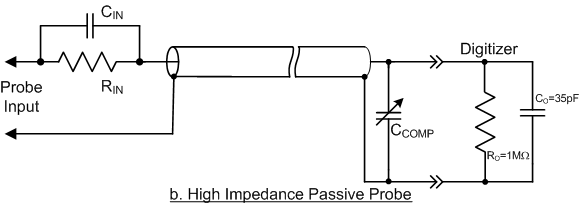 The high impedance passive probe uses a capacitively compensated voltage divider that divides the amplitude by a factor of typically ten to one (10:1). Such a compensated divider would result in an input capacitance of 10pF minimum with times ten attenuation, increasing the probe loading resistance by approximately 10x as shown in Figure 2.
Input capacitance could be further reduced by increasing the probe attenuation, but this would reduce the signal coming into the digitizer and make it more difficult to measure small signals. In practice, 10:1 attenuation generally represents a good compromise between signal amplitude and loading impedance.
This type of probe can have a bandwidth of up to 500 MHz. However, at higher frequencies even this lower value of probe capacitance can be too much. At 500 MHz a 10pF probe capacitance would be about 32 Ω which would load down the voltage of all but the lowest impedance circuits. At lower frequencies this is less of a problem.
The probe also attenuates the input voltage level by a factor of 10. This has to be accounted for in the digitizer output. This will be discussed later in the article.
Transmission line (low capacitance) Probes
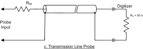 High frequency measurements require probes with very low input capacitance. The input capacitance can be drastically reduced by considering the coaxial cable as a transmission line. If the digitizer input is terminated in 50 Ω, the impedance looking into the probe end of the cable is a constant 50 Ω independent of frequency. This very low loading impedance can be increased using a voltage divider; a 450 Ω series resistor will divide the amplitude by ten times and result in a relatively constant loading impedance of 500 Ω. A low capacitance or transmission line probe, shown in Figure 3, utilizes a terminated transmission line.
The input capacitance of a transmission line probe such as this is quite low, typically about a small fraction of a pF. The limiting factor with this probe is the low input resistance. For a 10X probe the input resistance is only 500 Ω and may load circuits too heavily. These probes find application in high frequency designs where the circuits normally run on 50 Ω traces.
Active Probes
An active probe uses a compensated voltage divider driving an amplifier. The buffered output of the amplifier drives a coaxial cable terminated in its characteristic impedance just as was done in the transmission line probe. Here, it also isolates the probe from the capacitive loading of the cable and the input circuitry of the digitizer. These probes are normally powered and controlled by an oscilloscope. To use these probes with a digitizer the probe supplier needs to offer a stand-alone power supply and, if necessary, a control interface.
Selecting Passive Probes
High impedance passive probes are available in several attenuation factors. Attenuations of 10:1 and 100:1 are common. Working into the digitizers 1 MΩ input termination they offer 10 MΩ or 100MΩ input resistance. Digitizers with 14 to 16 bit resolution are well matched to the 100:1 probes as they have sufficient dynamic range to show small signals after the probe attenuation.
Probes have to be matched to the input capacitance of the digitizer. For a digitizer channel with a 35 pF input capacitance you have to select a probe with a compensation capacitance range that covers that capacitance.
Most high impedance passive probes use BNC type connectors. If the digitizer has BNC inputs that's great, but BNC connectors need a lot of space and digitizer front panels are often very small. You may need to use an adapter. For example, if the digitizer uses SMA connectors then an SMA to BNC adapter is required in order to mate with the probe.
Transmission line probes work into the digitizers 50 Ω input termination. Because the transmission line probes generally support bandwidths into the GHz range they usually use SMA connectors.
Sensors
Sensors or transducers are sensitive to a physical property and convert it into a voltage level proportional to the value of the property being measured. A common example is a current probe. It converts electrical current into an electrical voltage where the voltage level is proportional to the measured current level. Table 1 provides some common examples of sensors, along with the physical property sensed and the units of measure.
|
Sensor/Transducer Type |
Physical Property measured |
Typical Units of Measure |
|---|---|---|
| Current Sensors Current probe, Shunt, or Transformer |
Current | Ampere |
| Accelerometer | Acceleration | g's |
| Load or force cell | Force | Newtons or Pounds Force |
| Pressure Transducer | Pressure | Pascals or Pounds per square foot (psi) |
| Microphone | Sound Pressure Level | Pascals |
| Thermometer Thermocouple, Thermistor, or Resistance Temperature Detectors (RTD) |
Temperature | Degrees Celsius or Fahrenheit |
| Tachometer Optical pickup, Reluctance pickup |
Rotational Speed | Revolutions per minute (RPM) |
| Optical Sensors Photo diodes, Photo multipliers, Photo- Transistors, or CCD's |
Illuminance (Optical power incident on a surface) | Lux (lumens/m2) |
| Magnetic Fields Hall effect sensor |
Magnetic Flux Density (B) | Tesla |
| Particle Detectors Electron multipliers, Radiation detectors |
Radiation and particles | Count |
Sensor Interfacing
Matching a sensor or transducer to the digitizer requires knowledge of the sensor output range, output impedance, bandwidth, and sensitivity. The sensor output range must be within the voltage range of the digitizer or it may require attenuators or amplifiers to bring it into the digitizers range.
Most sensors are designed to work into a fixed impedance. Digitizers, like other measuring instruments, generally offer input terminations of 1 MΩ or 50 Ω. Most broad band transducers are designed to match 50 Ω load impedance. Lower bandwidth sensors may require a 1 MΩ load. Some specialized transducers may be designed to work into other impedances such as 75 or 600 Ω. In these cases matching pads may be required along with suitable adjustments to the sensor sensitivity.
The bandwidth of the digitizer should be significantly greater than the bandwidth of the sensor to avoid reducing the effective bandwidth of the sensor-digitizer system. A bandwidth ratio of digitizer to sensor bandwidth of greater than 7:1 will result in a 1 % or less uncertainty in amplitude measurements.
Sensitivity is the ratio of the given value of the sensors electrical output to the equivalent measured property. For instance, an accelerometers sensitivity may be specified as 10 mV/g. This means that for a measured physical input of 1 g the transducer outputs a 10 mV signal. Knowledge of the sensitivity is important when calibrating the digitizer to read in the measured units rather than electrical units.
Most transducers require a source of power. This is normally supplied externally to the digitizer. The transducer supplier is the source for power supplies and related interface electronics.
Examples of Probe and Sensors Applications - Using a Passive Probe with Rescaling
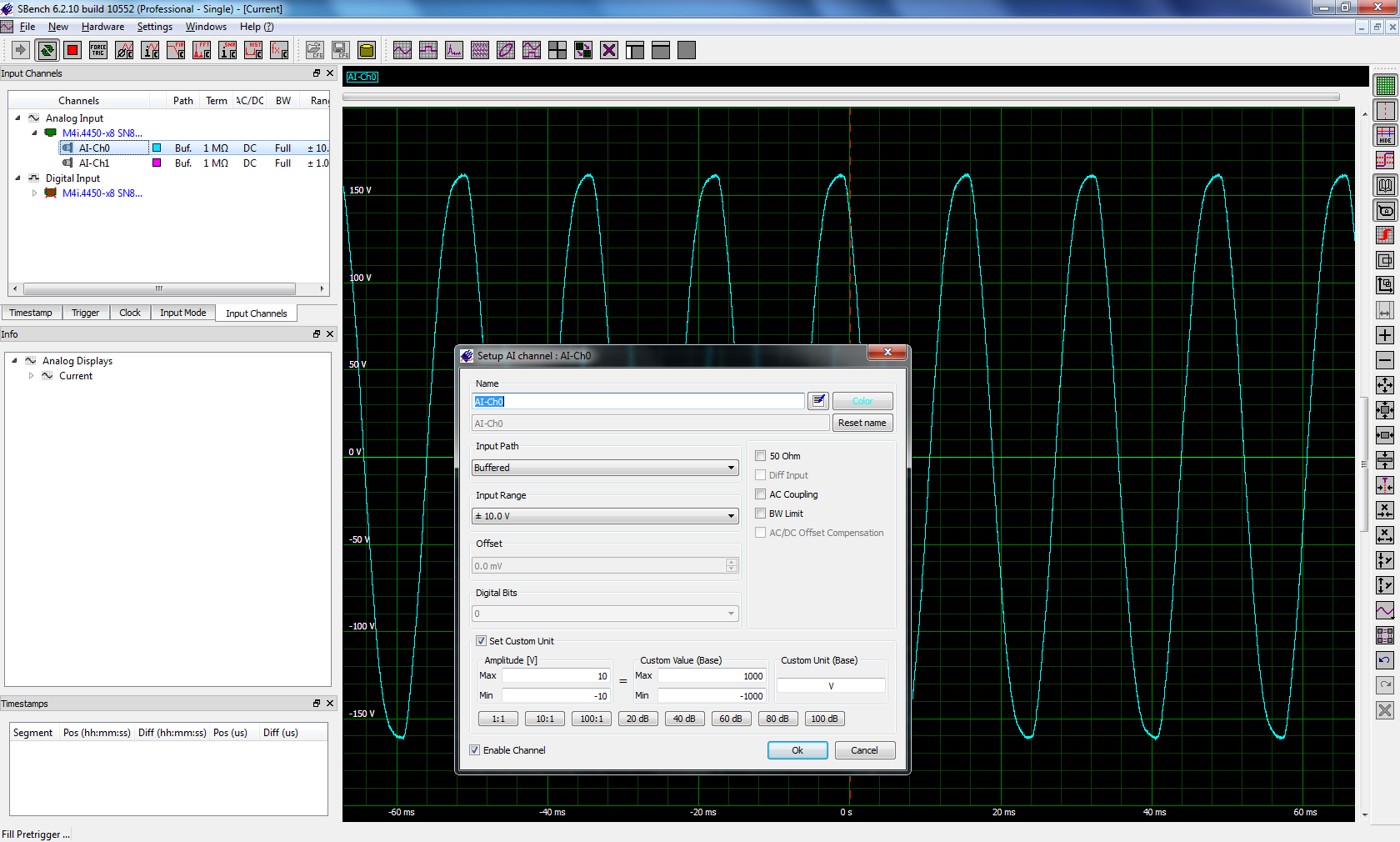 When you use passive probes with attenuation factors other than 1:1 then the voltage levels at the input of the digitizer will be attenuated. You can compensate for this attenuation by rescaling the input levels. If you are using Spectrum's SBench 6 software for control, acquisition and analysis this can easily be done in the analog channel setup as shown in Figure 4.
First, double click on the channel that is connected to the probe under the Analog Input list on the left side of the screen. This will bring up the Setup Channel pop up as shown. Click the Set Custom Unit check box and select probe attenuation (100:1 is selected in this example). Note that the maximum amplitude value of 10V is now reported as 1000V.
If you are using a third party or custom software package to control the digitizer you will have to make an appropriate adjustment in the vertical scaling.
Using a Current Probe with a Digitizer
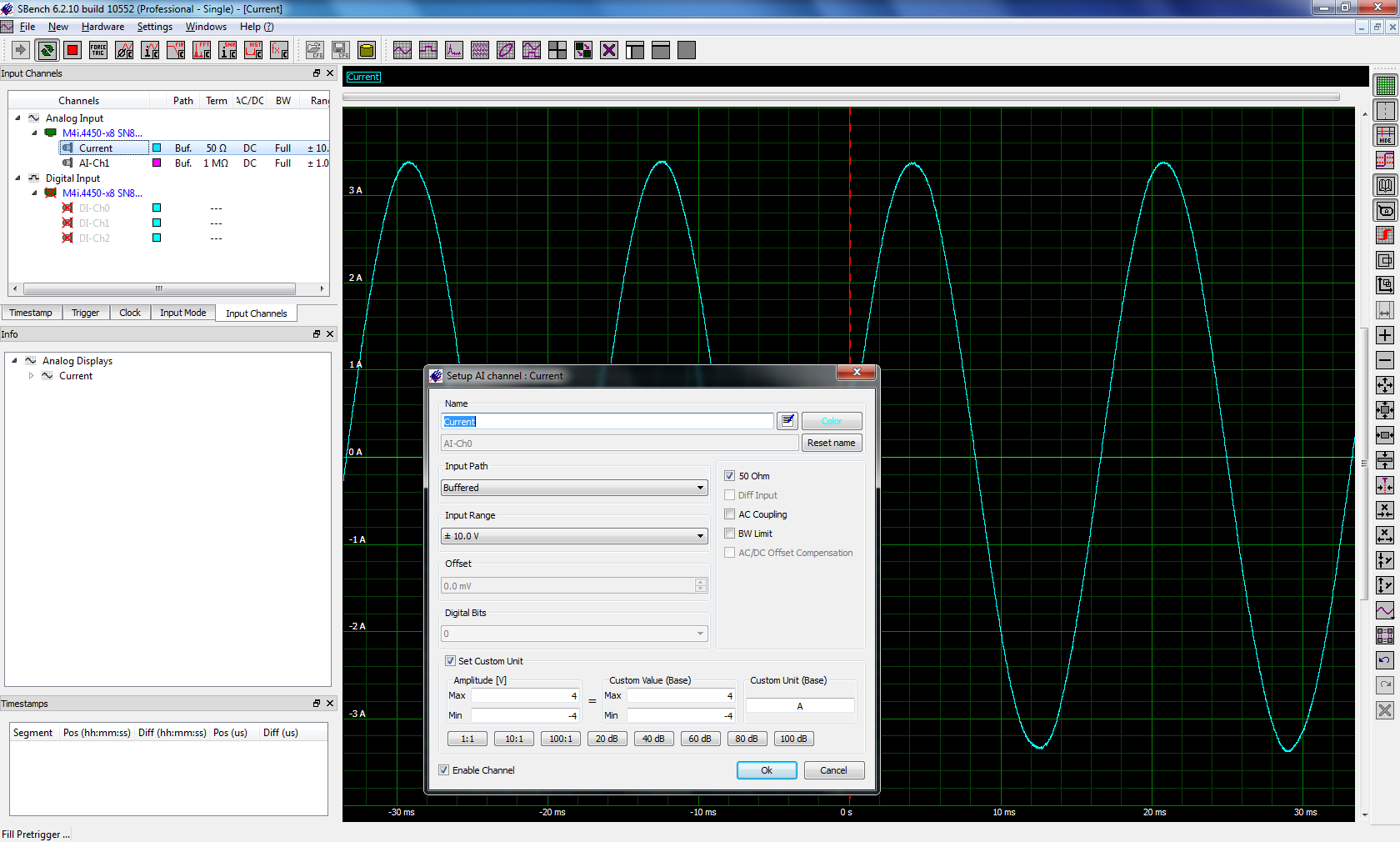 Stand-alone current probes include their own power source and controls for setting the current range, offset, and de-Gaussing (de-magnetizing the probe head). Most operate into a 50 Ω termination. The one used in this example had a sensitivity of 1 mV per mA. So the ± 200 mV full scale range in the digitizer would represent a ±200 mA current range. The Spectrum digitizer was set to 50 Ω termination with a full scale range of ±4V. As we did in the case of the passive probe in the previous example, double click on the channel using the current probe under the Analog Input list on the left side of the screen. This will bring up the Setup Channel pop up as shown in Figure 5.
Click the Set Custom Unit check box. The Amplitude (mV) box will show the maximum and minimum values for the digitizer range, in this case + 4 and -4 V respectively. Enter the desired maximum and minimum current range in the Custom Value (Base) box, in this example it is +4 and -4. Enter the units (A for Amperes in this Case) into the Custom Unit (Base) box. The digitizer scale for this channel is now reading in Amperes. The grid behind the Setup box shows a vertical scale calibrated in units of current.
Using a Pressure Transducer with a modular Digitizer
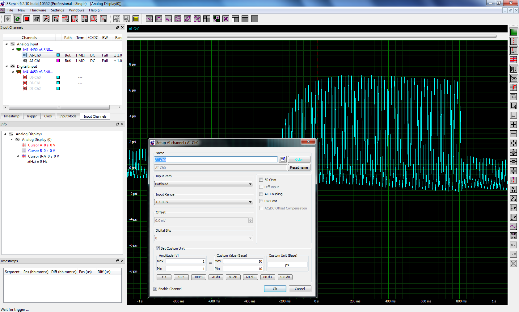 Piezo-electric transducers are a family of transducers based on electrical voltage being generated by compressing a crystal or ceramic element. Accelerometers place a known mass in contact with the piezo-electric element and the force on the element is proportional to the acceleration. A force or load cell measures force by applying it directly to the transducer element. The pressure uses a diaphragm in contact with the element where the force on it is proportional to pressure applied to the diaphragm. All of these transducers require an external power supply and most of them work into a 1 MΩ termination. Figure 6 shows the digitizer scaling for a piezo-electric pressure transducer.
The sensitivity of the pressure transducer is 100 mV per psi. Double clicking on the channel in SBench 6 brings up the Channel Setup. Check the Setup Custom Unit box. To read the measured waveform in units of psi enter the maximum range of +10 and the minimum range of -10 corresponding to the full scale input range of ±1 V. Enter the Custom Unit as psi, the vertical scale now show magnitudes in psi. If instead of psi vertical units of Pascal were desired the ±1V full scale range of the digitizer is equivalent to a pressure range of ± 68,947 Pa. This range can be entered into the SBench 6 Custom Value box along with the custom unit Pa.
Summary
With appropriate scaling, oscilloscope probes and other sensors can be used with any modular digitizer and data can be read in the desired custom physical units.