THIS PRODUCT IS OBSOLETE. Show more about end-life-products policy.

Recommended product:
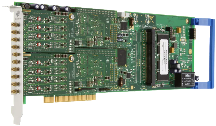
Product:
M2i.4912
16 bit multi-purpose digitizer
Description:
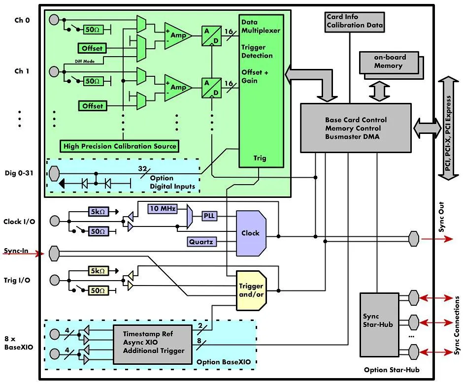
The M2i.49xx series allows recording of up to eight channels with sampling rates of 30 MS/s or four channels with sampling rates of 60 MS/s. These cards offer outstanding A/D features both in resolution and speed for PCI/PCI-X and PCI Express. The cards can be switched between Single-Ended inputs with a programmable offset and true differential inputs. If used in differential mode each two inputs are connected together reducing the number of available channels by half. The 16 bit vertical resolution have four times the accuracy compared to 14 bit cards and sixteen times the accuracy if compared with a 12 bit card. All boards of the M2i.49xx series may use the whole installed on-board memory of up to 1 GSamples, completely for the currently activated number of channels.
Facts & Features:
- Up to 10 MS/s on 8 channels (Single Ended)
- Up to 10 MS/s on 4 channels (Differential)
- Software selectable single-ended or differential inputs
- Simultaneously sampling on all channels
- Separate ADC and amplifier per channel
- Up to 1 GSample on-board memory
- 256 MSample standard memory installed
- 6 input ranges: +/-200 mV up to +/-10 V
- Programmable input offset of +/-100%
- Window, pulse width, re-arm, spike, OR/AND trigger
- 66 MHz 32 bit PCI-X interface
- 5V / 3.3V PCI compatible
- 100% compatible to conventional PCI >= V2.1
- Sustained streaming mode up to 245 MB/s
Product-Video:
Application examples:
BaseXIO (Optional)
The BaseXIO option offers 8 asynchronous digital I/O lines on the base card. The direction can be selected by software in groups of four. Two of these lines can also be used as additional external trigger sources. This allows the building of complex trigger conjunctions with external gated triggers as well as AND/OR conjunction of multiple external trigger sources like, for example, the picture and row synchronisation of video signals. In addition one of the I/O lines can be used as reference clock for the Timestamp counter.

FIFO mode
The FIFO mode is designed for continuous data transfer between measurement board and PC memory (up to 245 MB/s on a PCI-X slot, up to 125 MB/s on a PCI slot and up to 160 MB/s on a PCIe slot) or hard disk. The control of the data stream is done automatically by the driver on interrupt request. The complete installed on-board memory is used for buffer data, making the continuous streaming extremely reliable.
System Star-Hub (Optional)
Using the System Star-Hub for M2i series cards it is possible to synchronize several systems with each other having the same advantages that the standard Star-Hub gives. The system star-hub allows to extend the number of synchronous channels or set up multiple synchronous data streaming systems either for data storage or online calculations.
Star-Hub (Optional)
The star-hub is an additional module allowing the phase stable synchronization of up to 16 boards in one system. Independent of the number of boards there is no phase delay between all channels. The star-hub distributes trigger and clock information between all boards. As a result all connected boards are running with the same clock and the same trigger. All trigger sources can be combined with OR/AND allowing all channels of all cards to be trigger source at the same time. The star-hub is available as 5 card and 16 card version. The 5 card version doesn't need an extra slot.
Channel Trigger
The data acquisition boards offer a wide variety of trigger modes. Besides the standard signal checking for level and edge as known from oscilloscopes it's also possible to define a window trigger. Trigger conditions can be combined with logical conjunctions like OR to adopt to different application scenarios.

External Trigger
All boards can be triggered using an external TTL signal. It's possible to use positive or negative edge also in combination with a programmable pulse width. An internally recognized trigger event can - when activated by software - be routed to the trigger connector to start external instruments.


Spike Trigger
The trigger event is a slope inside the signal that is larger (or even smaller) than a programmed slope. Internally the difference of two adjacent samples is calculated and then compared to the programmed trigger level. This trigger mode allows the detection of signal distortions as needed for power line monitoring.
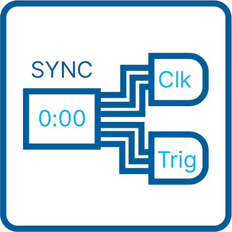
Timestamp
The timestamp option writes the time positions of the trigger events in an extra memory. The timestamps are relative to the start of recording, a defined zero time, externally synchronized to a radio clock, or a GPS receiver. With this option acquisitions of systems on different locations can be set in a precise time relation.
External Clock
Using a dedicated connector a sampling clock can be fed in from an external system. It's also possible to output the internally used sampling clock to synchronize external equipment to this clock.

High Precision PLL
The internal sampling clock of the card is generated using a high precision PLL. This powerful device allows to select the sampling rate with a fine step size making it possible to perfectly adopt to different measurement tasks. Most other cards on the market only allow the setup of fixed sampling rates like 100 MS/s, 50 MS/s, 25 MS/s, 10 MS/s, ... without any possibility to set the sampling rate to any value in between.
Reference Clock
The option to use a precise external reference clock (normally 10 MHz) is necessary to synchronize the board for high-quality measurements with external equipment (like a signal source). It's also possible to enhance the quality of the sampling clock in this way. The driver automatically generates the requested sampling clock from the fed in reference clock.
On-board Calibration
The on-board calibration can be run on user request and calibrates the amplifier against a dedicated internal high precision calibration source. After this calibration data is stored permanently in an on-board EEPROM and is automatically used for further acquisitions.

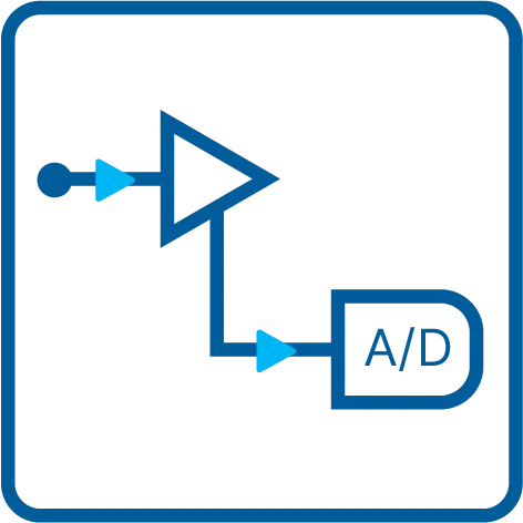
Differential Inputs
With a simple software command the inputs can individually be switched from single-ended (in relation to ground) to differential, without loosing any inputs. When the inputs are used in differential mode the A/D converter measures the difference between two lines with relation to system ground.

Digital Inputs (Optional)
This option acquires additional synchronous digital channels phase-stable with the analog data. When the option is installed there are 16/32 additional digital inputs which can be individually mulitplexed into the analog data in different formats reducing the analog resolution.

Programmable Input Amplifiers
The analog inputs can be adapted to real world signals using a wide variety of settings that are individual for each channel. By using software commands the input termination can be changed between 50 Ohm and 1 MOhm and one can select an input range matching the real world signal.
Programmable Input Offset
Most of the Spectrum A/D cards offer a user programmable signal offset opening the Spectrum boards to a wide variety of setups. The signal offset at least covers a range of +/-100 % of the currently selected input range making unipolar measurements with the card possible. Besides this the input range offset can be programmed individually allowing a perfect match of the A/D card section to the real world signal.


This standard driver is included in the card delivery and it is possible to get the newest driver version free of charge from our homepage at any time. There are no additional SDK fees for the classical text-based programming. All boards are delivered with drivers for Windows 7, Windows 8, Windows 10 and Windows 11, all 32 bit and 64 bit.
| Product | Channels | Max. Samplerate | Max. Bandwidth |
|---|---|---|---|
| M2i.4911 | 4 | 10 MS/s | 5 MHz |
| M2i.4931 | 4 | 30 MS/s | 15 MHz |
| M2i.4932 | 8 | 30 MS/s | 15 MHz |
| M2i.4960 | 2 | 60 MS/s | 30 MHz |
| M2i.4961 | 4 | 60 MS/s | 30 MHz |
| M2i.4963 | 4 | 60 MS/s | 30 MHz |
| M2i.4964 | 8 | 60 MS/s | 30 MHz |
| On different platforms | Bus | Max. Bus Transfer speed |
|---|---|---|
| DN2.491-08 | Ethernet | 70 MByte/s |
| DN2.491-16 | Ethernet | 70 MByte/s |
| DN6.491-24 | Ethernet | 70 MByte/s |
| DN6.491-32 | Ethernet | 70 MByte/s |
| DN6.491-40 | Ethernet | 70 MByte/s |
| DN6.491-48 | Ethernet | 70 MByte/s |
| M2i.4912-Exp | PCI Express x1 | 160 MByte/s |
| MC.4912 | CompactPCI | 100 MByte/s |
Clock / Trigger Distribution (Optional)
The Clock and Trigger Distribution card allows to externally connect several systems with a common clock and a synchronized trigger signal. One can connect up to 17 independent systems or external equipment using this card.
Docking Stations (Optional)
All Spectrum products can be used in 3rd party docking stations, connected by either PCIe interface card or by Thunderbolt interface. Docking stations can extend a standard PC by up to 16 PCIe slots.Documents
Windows driver installation of driver versions < 4.0 |
21.02.2022 | 1 M | ||
Data sheet of the M2i.49xx family |
21.02.2022 | 887 K | ||
Manual of M2i.49xx family |
21.02.2022 | 7 M | ||
Product Discontinuance Notification for M2i.49xx Series |
21.02.2022 | 246 K | ||
Datasheet of Spectrum Terastore Streaming System |
21.02.2022 | 910 K | ||
M2i Clock / Trigger distribution card |
21.02.2022 | 217 K | ||
M2i StarHub module datasheet |
21.02.2022 | 224 K | ||
Data sheet of SPA pre-amplifier |
08.12.2023 | 580 K | ||
Data sheet of Docking Station |
21.02.2022 | 166 K | ||
Short Manual for IVI Driver |
21.02.2022 | 532 K | ||
Data sheet of SBench 6 |
15.01.2024 | 999 K | ||
Manual for MATLAB driver M2p/M4i/M4x/M5i/M2i/M3i/DN2/DN6 |
13.12.2023 | 1 M | ||
Manual for LabVIEW drivers for M2i/DN2 |
21.02.2022 | 2 M | ||
Manual for SBench 6 |
21.02.2022 | 7 M |
WINDOWS DRIVER + SOFTWARE
M2i / M3i driver - last Version for Windows 2000 |
2 | 21.02.2022 | 437 K | |
M2p/M4i/M4x/M5i/M2i/M3i/DN2/DN6 driver for Windows 7, 8, 10, 11 (32/64 bit) |
7.01 | 22.04.2024 | 5 M | |
M2i/M3i/M4i/M4x driver - last Version for Windows 32 XP / Vista |
3.30 | 21.02.2022 | 2 M | |
M2i/M3i/M4i/M4x driver - last Version for Windows 64 XP / Vista |
3.20 | 21.02.2022 | 3 M | |
C/C++ driver header and library files |
7.01 | 22.04.2024 | 43 K | |
Spectrum Control Center - last Version for Windows 2000 |
1.41 | 21.02.2022 | 8 M | |
SBench 5 Installer |
5.3.0 | 21.02.2022 | 5 M | |
Spectrum Control Center (32-bit) / Windows 7, 8, 10 |
2.36 | 22.04.2024 | 22 M | |
Spectrum Control Center (64-bit) / Windows 7, 8, 10, 11 |
2.36 | 22.04.2024 | 25 M | |
Spectrum Control Center - last Version for Windows XP |
1.74 | 21.02.2022 | 8 M | |
SBench 6 (32-bit) Installer / Windows 7, 8, 10 |
6.5.08 | 22.04.2024 | 36 M | |
SBench 6 (64-bit) Installer / Windows 7, 8, 10, 11 |
6.5.08 | 22.04.2024 | 39 M | |
SBench6 - last Version for Windows XP |
6.3.5 | 21.02.2022 | 41 M | |
Windows Installer for Remote Server Option |
22.04.2024 | 13 M | ||
IVI Driver for IVI Digitizer class (32 bit) |
22.04.2024 | 3 M | ||
IVI Driver for IVI Scope class (32 bit) |
22.04.2024 | 3 M | ||
M2i/M2p/M3i/M4i/M4x/M5i/DN2/DN6 LabView driver installer |
22.04.2024 | 19 M | ||
M2p/M4i/M4x/M5i/M2i/M3i/DN2/DN6 Matlab driver + examples installer |
22.04.2024 | 15 M | ||
Windows Examples (C/C++, .NET, Delphi, Java, Python, Julia ...) |
7.01 | 22.04.2024 | 2 M |
LINUX DRIVER + SOFTWARE
M2p/M4i/M4x/M5i/M2i/M3i drivers (Kernel + Library) for Linux 32 bit and 64 bit |
7.01 | 22.04.2024 | 12 M | |
Driver libraries (no Kernel) for Linux 32 bit and 64 bit |
7.01 | 22.04.2024 | 9 M | |
Spectrum Remote Server Linux Installer Package |
22.04.2024 | 12 K | ||
Spectrum Control Center |
2.36 | 22.04.2024 | 57 M | |
SBench 6 Linux 32 (.rpm) |
6.5.08 | 22.04.2024 | 26 M | |
SBench 6 Linux 64 (.rpm) |
6.5.08 | 22.04.2024 | 26 M | |
SBench 6 Linux 32 (.deb) |
6.5.08 | 22.04.2024 | 23 M | |
SBench 6 Linux 64 (.deb) |
6.5.08 | 22.04.2024 | 22 M | |
SBench6 Jetson (.deb) |
6.5.08 | 22.04.2024 | 11 M | |
Drivers + examples for MATLAB for Linux (DEB + RPM) |
22.04.2024 | 183 K | ||
Linux Examples (C/C++, Python, Julia ...) |
7.01 | 22.04.2024 | 560 K |
Firmware
M2i/M2p/M3i/M4i/M4x/M5i firmware update (Windows) |
22.04.2024 | 22 M | ||
M2i/M2p/M3i/M4i/M4x/M5i firmware update (Linux) |
22.04.2024 | 30 M |
Case Studies
| OCT Skin Cancer Scanner | OCT application for skin cancer diagnosis |
21.02.2022 | 351 K | |
| CS Automotive Data Recorder | Case Automotive Data Study Recorder and Playback Solution |
21.02.2022 | 278 K | |
| CS DIAL - Differential Absorption LIDAR | Case Study DIAL - Differential Absorption LIDAR |
22.02.2022 | 2 M | |
| CS Time Reversal Focusing | Case Study: High Amplitude Time Reversal Focusing of Acoustic Waves |
21.02.2022 | 6 M | |
| CS Fusion Research | Case Study: Digitizers from Spectrum in Fusion Research |
21.02.2022 | 2 M |
Product Notes
| General Digitizer Introduction | General Introduction to Waveform Digitizers |
21.02.2022 | 587 K | |
| High-Res High BW Digitizers | Advantages of High Resolution in High Bandwidth Digitizers |
21.02.2022 | 2 M | |
| Digitizer Acquisition Modes | Using modular Digitizer Acquisition Modes |
21.02.2022 | 3 M | |
| Digitizer Front-End | Proper Use of Digitizer Front-End Signal Conditioning |
21.02.2022 | 3 M | |
| Trigger and Sync | Trigger, Clock and Synchronization Details at high-speed Digitizers |
21.02.2022 | 1 M | |
| Digitizer Software Integration | Software Support for Modular Digitizers |
21.02.2022 | 724 K | |
| SBench 6 Introduction | SBench 6 - Data Acquisition and Analysis of Digitizer Data |
21.02.2022 | 1 M | |
| PN 16 Bit Digitizer Comparison - high precision design | Product Note: Designing PCIe Digitizers for very high precision measurements |
21.02.2022 | 696 K |
Application Notes
| Ultrasonic Applications | Using Digitizers in Ultrasonic Applications |
21.02.2022 | 617 K | |
| Signal Processing Tools | Using Signal Processing Tools to enhance Digitizer Data |
21.02.2022 | 1 M | |
| Mechanical Measurements | Mechanical Measurements Using Digitizers |
21.02.2022 | 1 M | |
| Power Measurements | Power Measurements Using Modular Digitizers |
21.02.2022 | 1 M | |
| Using Probes & Sensors | Using Probes and Sensors with Modular Digitizers |
21.02.2022 | 858 K | |
| Digitizers as Oscilloscope | Using a Digitizer as Oscilloscope |
21.02.2022 | 845 K | |
| Solving Data Transfer Bottlenecks on Digitizers | Solving Data Transfer Bottlenecks on Digitizers |
21.02.2022 | 2 M | |
| Teaming AWG with Digitizer | Teaming an Arbitrary Waveform Generator with a Modular Digitizer |
21.02.2022 | 919 K | |
| Common Digitizer Setup Problems | Application Note: Common Digitizer Setup Problems to avoid |
21.02.2022 | 1 M | |
| Mechanical Measurements D | Mechanische Messungen mit modularen Digitizern |
21.02.2022 | 1 M | |
| Mass Spectroscopy | Application Note Mass Spectroscopy |
21.02.2022 | 879 K | |
| AN Vehicular Testing with Modular Instruments | Application Note: Vehicular Testing with Modular Instruments |
21.02.2022 | 1 M | |
| AN LIDAR Light Detection and Ranging | Application Note LIDAR - Light Detection and Ranging |
21.02.2022 | 528 K | |
| AN Testing Power Supplies | Application Note: Testing Power Supplies using Modular Digitizers |
21.02.2022 | 898 K | |
| AN Amplitude Resolution | Application Note: The Amplitude Resolution of Digitizers and how it affects Measurements |
21.02.2022 | 555 K | |
| AN008 Install Legacy Win Drivers | Application Note: Legacy Windows Driver Installation |
21.02.2022 | 1 M |