-
Comparisons
-
Hardware Features
-
Systems
-
Software
-
Company
Knowledge-Base
- Hardware Features
- Acquisition Modes
Gated Sampling
![]()
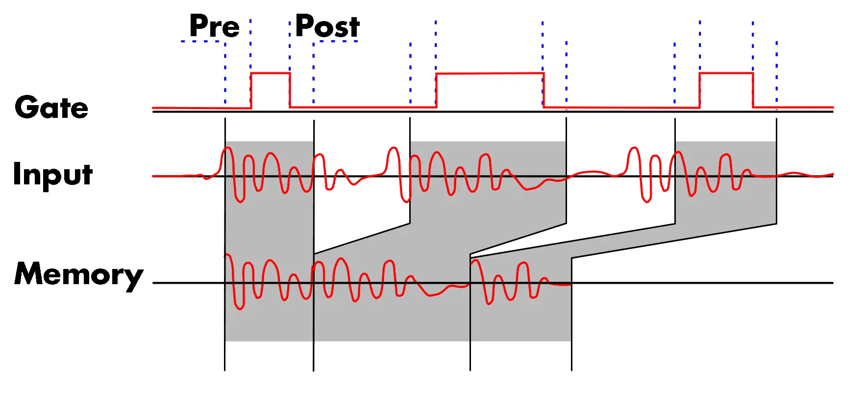
 Gated acquisition uses the state of a gating (enabling) signal, which can be either another channel or an external trigger input, to start and stop the sampling process. Data is only written to memory while the gate is active. As in the Multiple Recording mode, the user can program pre- and post-trigger intervals about the gate. In Gated mode the timestamps mark the opening and closing of the gate not including the pre and post gate acquisition interval. The number of acquired gate segments is limited by the acquisition memory and is only limited by the host memory when using FIFO mode.
Significant data associated with multiple triggers is stored in the acquisition memory in the contiguous segments. Data associated with the dead-time between events is not recorded. Each trigger event is time stamped so the precise location of each trigger is known. The timestamps are stored in an extra FIFO memory that is located in hardware on the card. It can be read out if needed much as the data is.
Advantages of Gated Sampling Mode
- The re-arm or trigger ?dead-time? is reduced extremely in multiple and gated modes compared with single-shot acquisitions. A low trigger re-arm time means you reduce the chance of missing an event even in high event rate applications.
- Segmentation of the acquisition memory allows more efficient use of memory by recording data at full sample rate only when the signal is active which is indicated by the gate signal.
- The storage of only significant measurement events without the intervening ?dead? time results in less data to be transferred and allows continuous data acquisition and processing of segmented signals.
- The Timestamp of each gate start and gate stop event allows you to read the time difference between events and the length of a gate segment. When the events represent abnormalities in the signal, timestamps provide information on the rate of occurrence of the anomalies.
- Timestamps can by synchronized to an external reference signals such as a radio clock or IRIG-B timing generator to get UTC synchronized timestamp information on every event.
Example
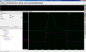
 The right hand figure provides an example of a Gated acquisition being used with a simulated laser signal. The gate signal marks the laser being triggered. The gate signal has been applied to the second channel of the digitizer and that channel is set up as the trigger source. The trigger threshold level is set to be 150 mV. The resultant acquisition includes both the laser pulse and the gate signal on the display. Note that a pre and post area of 128 samples adds additional samples to the gate area. When using the Gated acquisition mode the timestamps are associated with the start and stop edges of the gate. This is seen on the zoom view of the segment. Segment duration is equal to the gate time plus the 128 samples of the pre and post gate areas.
Use of the Gated acquisition mode allows the capture of eighteen pulses (with a total duration of 1.8s) using only 8kS of acquisition memory.
Re-Arm time (dead time)
The re-arm time is the dead time between the end of one segment acquisition and the potential start of the next segment acquisition. During this dead time the data acquisition card is not able to detect a trigger and a potential event will get lost. A short dead time is a key feature for this mode. While competitor products have dead times that can be up to several us or even ms the Spectrum cards have a short dead time that is a fixed number of samples and therfore directly related to the sampling rate. More info on re-arm time
Limitations of MICX platform in Multiple Recording Mode
This chapter is valid for all products based on MICX platform driver. Read More
Products based on the MICX platform do not have a programmable pretrigger or posttrigger area in Gated Sampling mode. Instead the pretrigger is a small fixed number of samples. The size of the pretrigger inhere depends on the speed and number of activated channel and can be found in the hardware manual.